Here is how to make a SIMCOM 7600 module work on an Arduino board (Uno, Mega 2560, Leonardo, Due, Micro, Zero, Nano, Pico), ESP8266, ESP32, Raspberry Pi Pico, MicroPython, or any other microcontroller.
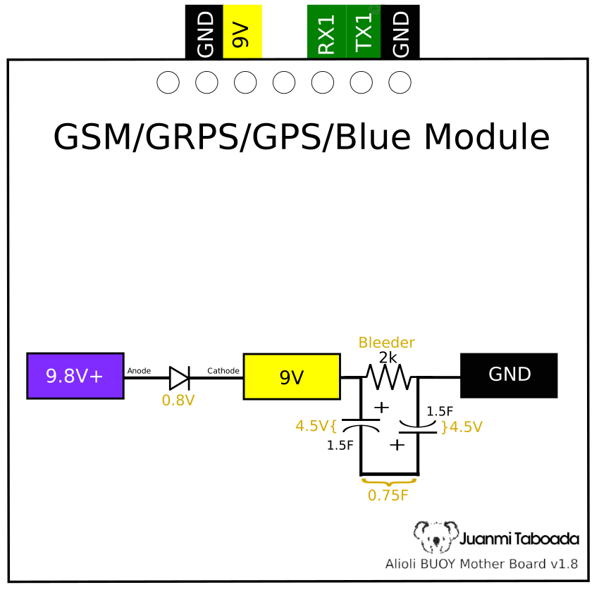
If your module accepts 5-10V, the short answer is the following diagram:
SIMCOM SIM7600 GSM/GPRS/GPS/Bluetooth Module Power Schema and Diagram Connections
SIMCOM SIM7600 GSM/GRPS/GPS/Bluetooth Modules will consume a peak current of 2A when communicating with the network. Most probably, your power source can not provide that current. I had those problems using a power supply connected to my home electricity that technically provides 10A, do not despair.
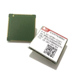
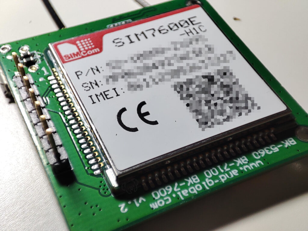
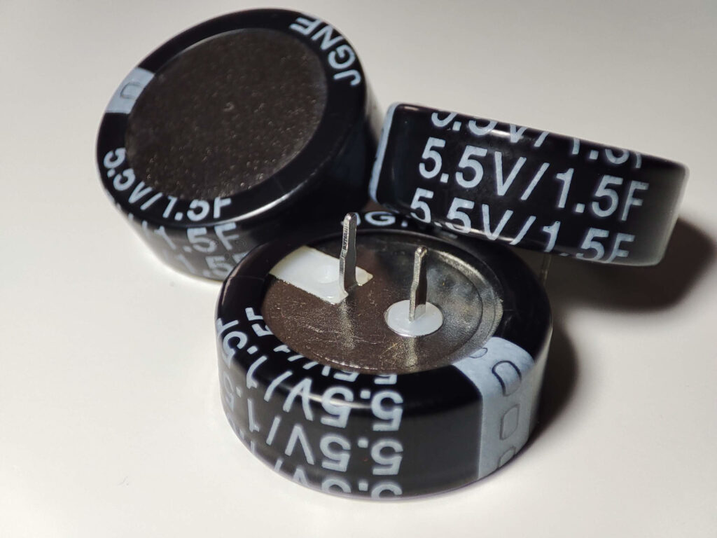
The solution is to add a couple of supercapacitors before feeding the module. The SIMCOM module I am using is a SIM7600E-H1C. I tested with other SIM7600 modules with similar success.
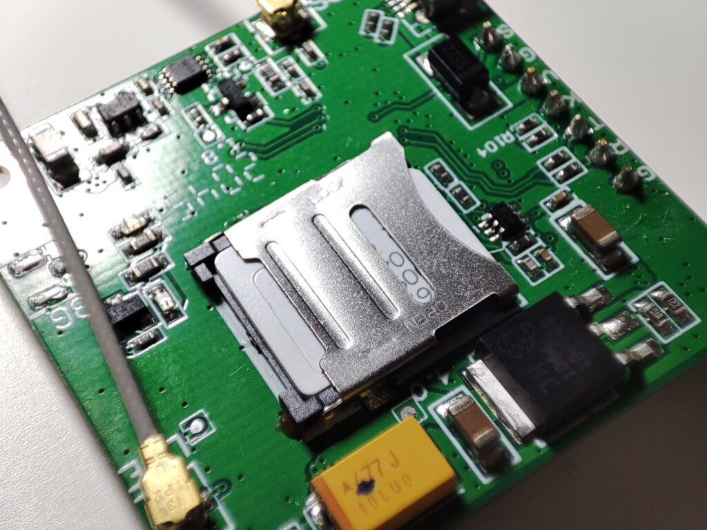
SIMCOM GSM GPRS GPS MODULE SIM 7600E-H1C Front ViewSIMCOM GSM GPRS GPS MODULE SIM 7600E-H1C Back ViewSupercapacitors 5.5V and 1.5F
WARNING: Before connecting any capacitor or supercapacitor, ensure the details of your ones. Every capacitor has a “polarity” and a working “voltage”. If you supply a higher voltage to your capacitor than what it is specified, it may “EXPLODE”.
Circuit explained
The SIMCOM module I am using accepts from 5V to 10V.
A higher voltage will make the supercapacitors charge quicker
I feed the circuit with 9.8V from a power regulator.
The diode will decrease the voltage to 0.8V, preventing the capacitors from feeding the circuits before our module.
After the diode, we have 9V.
Then we have to connect the supercapacitors. Mines are 1.5F at 5.5V.
When connected in series, the voltage is divided by both supercapacitors, so if we have 9V at the entry, we will have 4.5V on each supercapacitor. Therefore, they will work in a safe area (4.5V) below the 5.5V specified for the supercapacitors. I will explain below how to calculate details for your supercapacitors.
Since we have connected them in series, their total capacity is now 0.75F, which for my SIMCOM module has been enough to perform with no problem.
The 2k resistor is a bleeder resistor that will consume the power stored in the supercapacitors when the system shuts down. You can use a larger resistor, but not a smaller one, since it will get hot and burn.
Connect the module to 9V and GND to get it working.
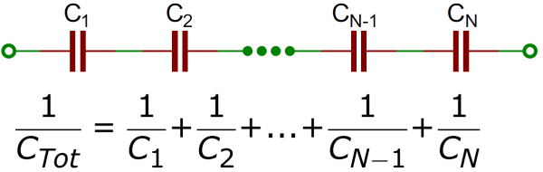
Capacitors equations
Capacitors in series
For 2 equal capacitors the equations will look like:
VT = VC1 + VC2
CT = (C1 * C2) / (C1 + C2)
For 9V power supply:
VT = 9V
VT = VC1 + VC2 (where VC1=Q/C1 and VC2=Q/C2 and C1=C2 so Q/C=VC1=VC2=VC)
VT = 2VC
VC = VT / 2
VC = 9V / 2
VC = 4.5V = VC1 = VC2
VC1 = 4.5V and VC2 = 4.5VFor 2 supercapacitors of 1.5F each with 9V power supply:
CT = (C1 * C2) / (C1 + C2)
CT = (1.5F * 1.5F) / (1.5F + 1.5F)
CT = 2.25F / 3F
CT = 0.75F
Now you can check on YELLOW the results from these equations:
SIMCOM SIM7600 GSM/GPRS/GPS/Bluetooth Module Power Schema and Diagram Connections
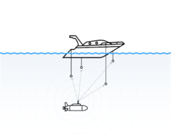
This time I have decided to write this article in English because I have been able to get a lot of information. Thanks to that, most of the information I found to help me with this project was in English. A long time ago, I tried scuba diving, and after some time, I decided to […]
I will tell you about my experience repairing a cargo ship as a naval Engineer. Some months ago, you could read in the local newspaper Málaga Hoy that a large cargo ship was approaching Málaga after a major accident it had suffered in its front part. It was the cargo ship Integrador with a Panamanian […]