Alioli ROV Boards
In my last post, “Get your hardware for Arduino Underwater ROV”, I described most of the hardware I use to build Alioli ROV and how I plan to use it. In this post, I...
Filter by Category
Filter by Author

In my last post, “Get your hardware for Arduino Underwater ROV”, I described most of the hardware I use to build Alioli ROV and how I plan to use it. In this post, I...
Posted by Juanmi Taboada

In my last post, “Finishing the frame for an Underwater ROV”, I gave all details about the design I used to build the frame for Alioli Underwater ROV. In this post, I...
Posted by Juanmi Taboada

In my last post, “How I designed the frame for my Underwater ROV“, I gave all details about the design I used for the frame for Alioli Underwater ROV. In this post, I...
Posted by Juanmi Taboada
In my last post, “Underwater Alioli ROV“, I shared all the information I got from the Internet to build my Underwater ROV. In this post, I will explain how I made the...
Posted by Juanmi Taboada

This time I have decided to write this article in English because I have been able to get a lot of information. Thanks to that, most of the information I found to help me with...
Posted by Juanmi Taboada

🇬🇧 Read it in English, “GenCreate, GenUpdate, GenDetail and GenDelete“ En el último artículo describíamos Codenerix GenList para comenzar a usar los listados de CODENERIX. Ha...
Posted by Juanmi Taboada

🇬🇧 Read it in English, “GenList“ Anteriormente hablábamos sobre CodenerixModel para entender como se construye un modelo funcional con CODENERIX. Sin embargo, para que...
Posted by Juanmi Taboada

🇬🇧 Read it in English, “CodenerixModel“ En el artículo anterior hablábamos sobre CODENERIX y sus bondades. Ahora vamos a comenzar una serie de artículos que permitan...
Posted by Juanmi Taboada

Tal y como Google anunciaba en su blog oficial, aquellos usuarios que accedan al calendario desde la web comenzarán a ver un nuevo diseño mucho más limpio basado en el estándar de...
Posted by Juanmi Taboada

Poodle se convierte en una amenaza para la red, se recomienda desactivar SSL3 del navegador. Hace tan sólo 2 días Google reveló una nueva vulnerabilidad que afecta a la...
Posted by Juanmi Taboada

In my last post, “Get your hardware for Arduino Underwater ROV”, I described most of the hardware I use to build Alioli ROV and how I plan to use it. In this post, I will show how the hardware interconnects with each other and the boards I have built.
During the process of building Alioli ROV, I went through several changes, most of them because I learned from the experience and improved the process of soldering and implementing boards. For example, I started building my boards in the latest integrations because it made it easier to keep the table clean and more comfortable since I didn’t have so many cables on my table.
Table of Contents
ToggleThe mainboard for the Alioli ROV is an Arduino Mega 2560 R3:
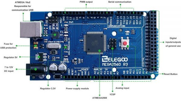
The power I will need for Alioli ROV is:
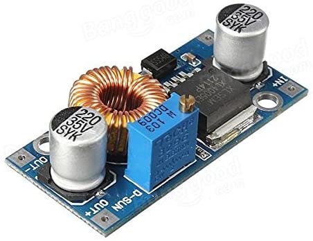
I need 12V (motors), so I use a Voltage Stabilizer from 12V to 5V (HW-638) and a Voltage Converter from 5V to 3.3V. Engines will get their power straight from the battery since the rest of the system will get their power from the Voltage Stabilizer. In this way, I am protecting the circuit from the noise of the motors when they start and stop. After the voltage stabilizer, it will be a Reducer Regulator Module from 5V to 3.3V to provide 3.3V to any circuit that needs it.

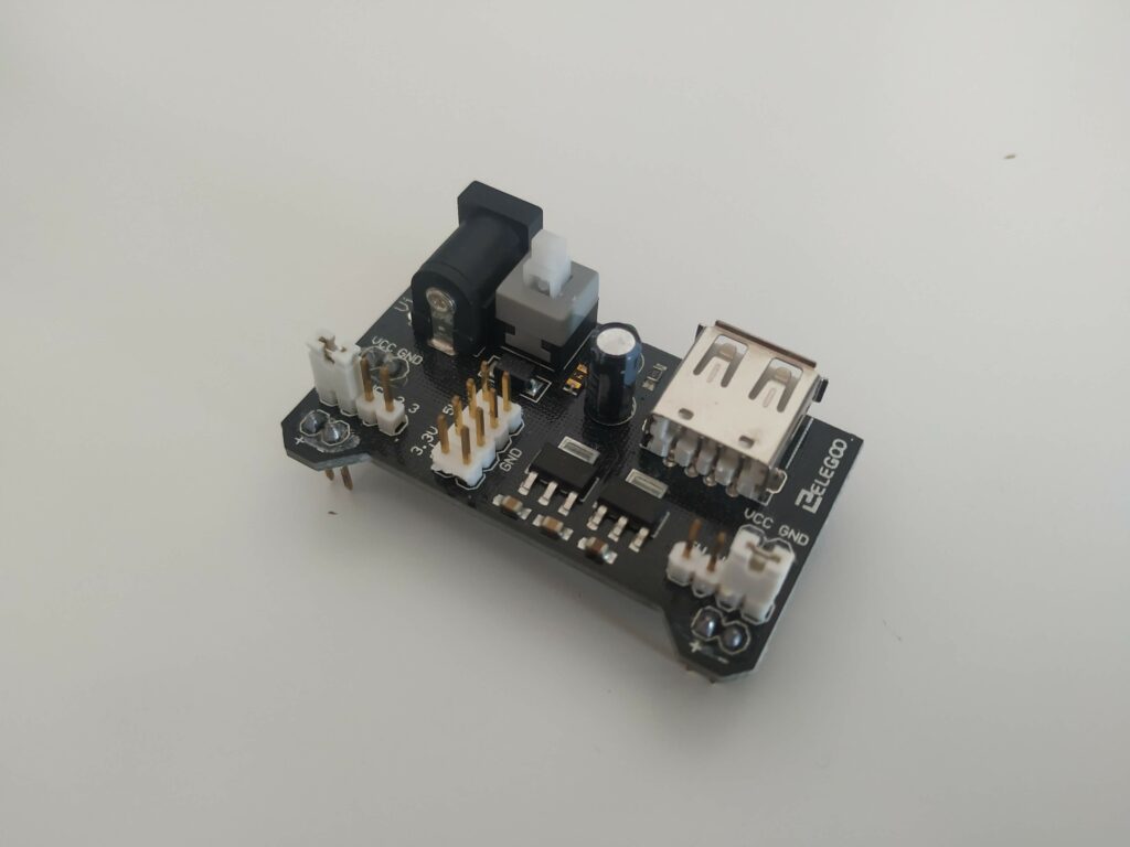
I decided to build 2 boards: the first is to reuse the Arduino Power Supply Module from the kit I bought. Hence, it provides me with several pins at the same voltage level, and I can also use the switch to power on and off during tests. The second board is the one I will use when the testing phase finish.
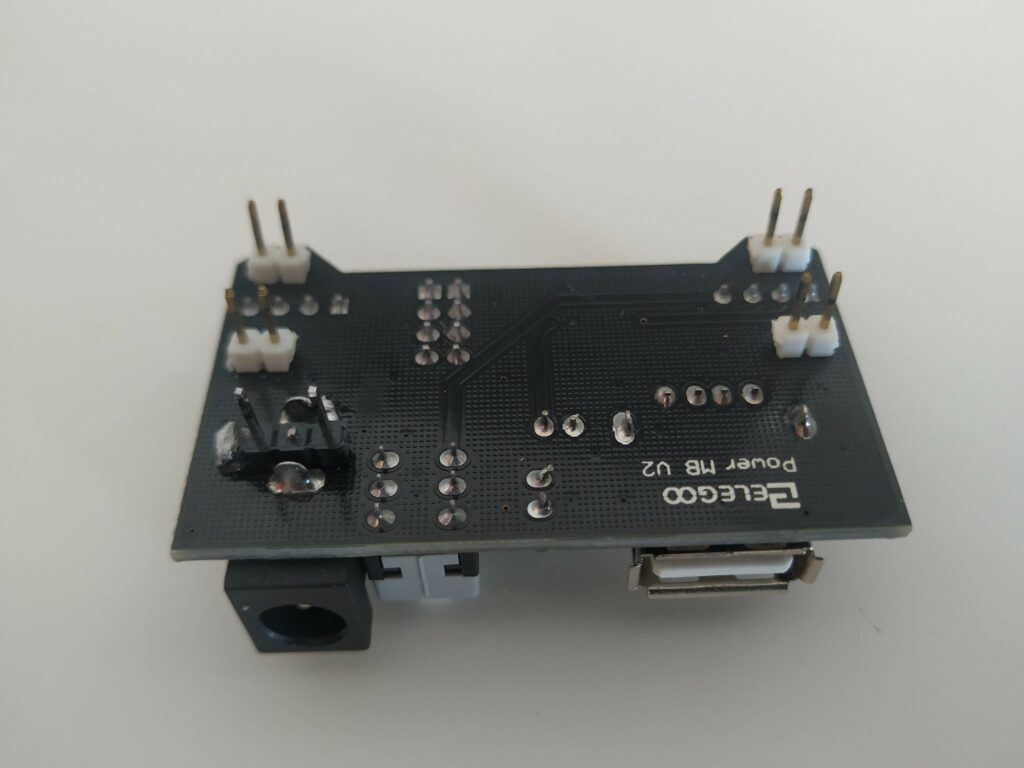
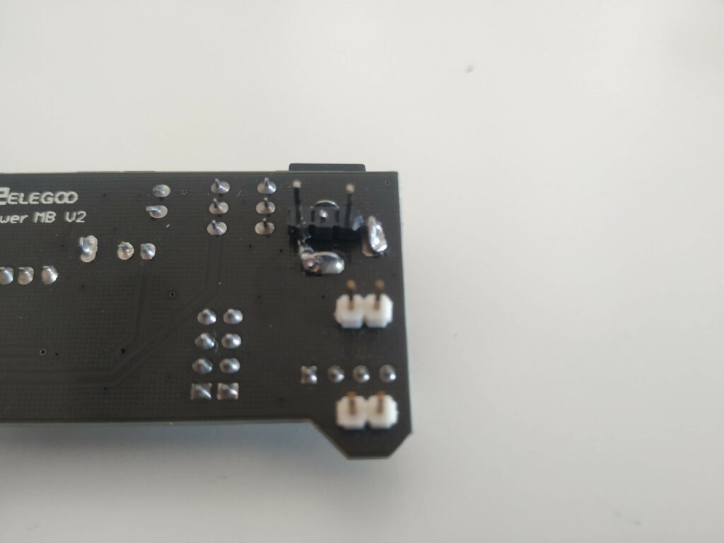
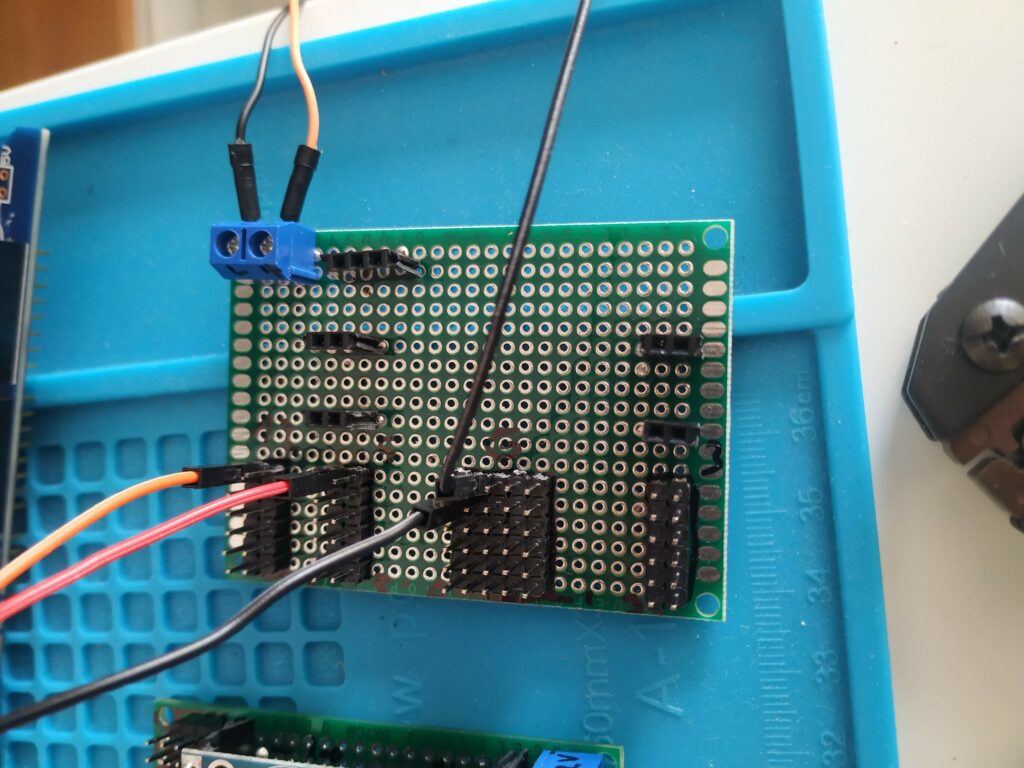
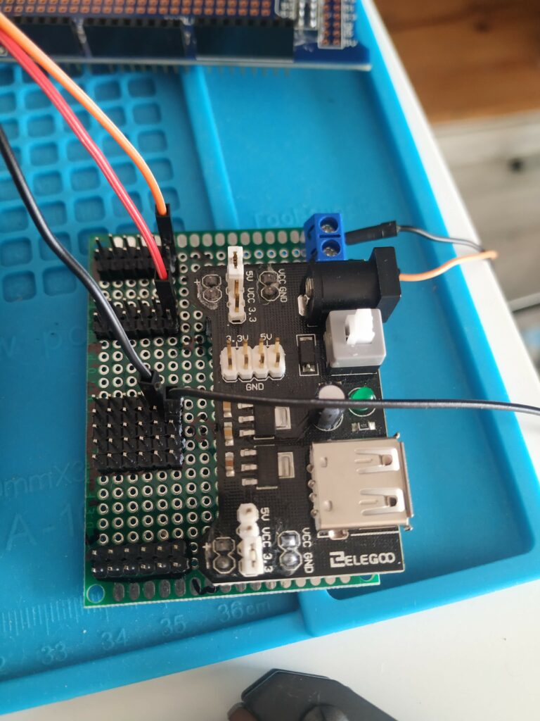
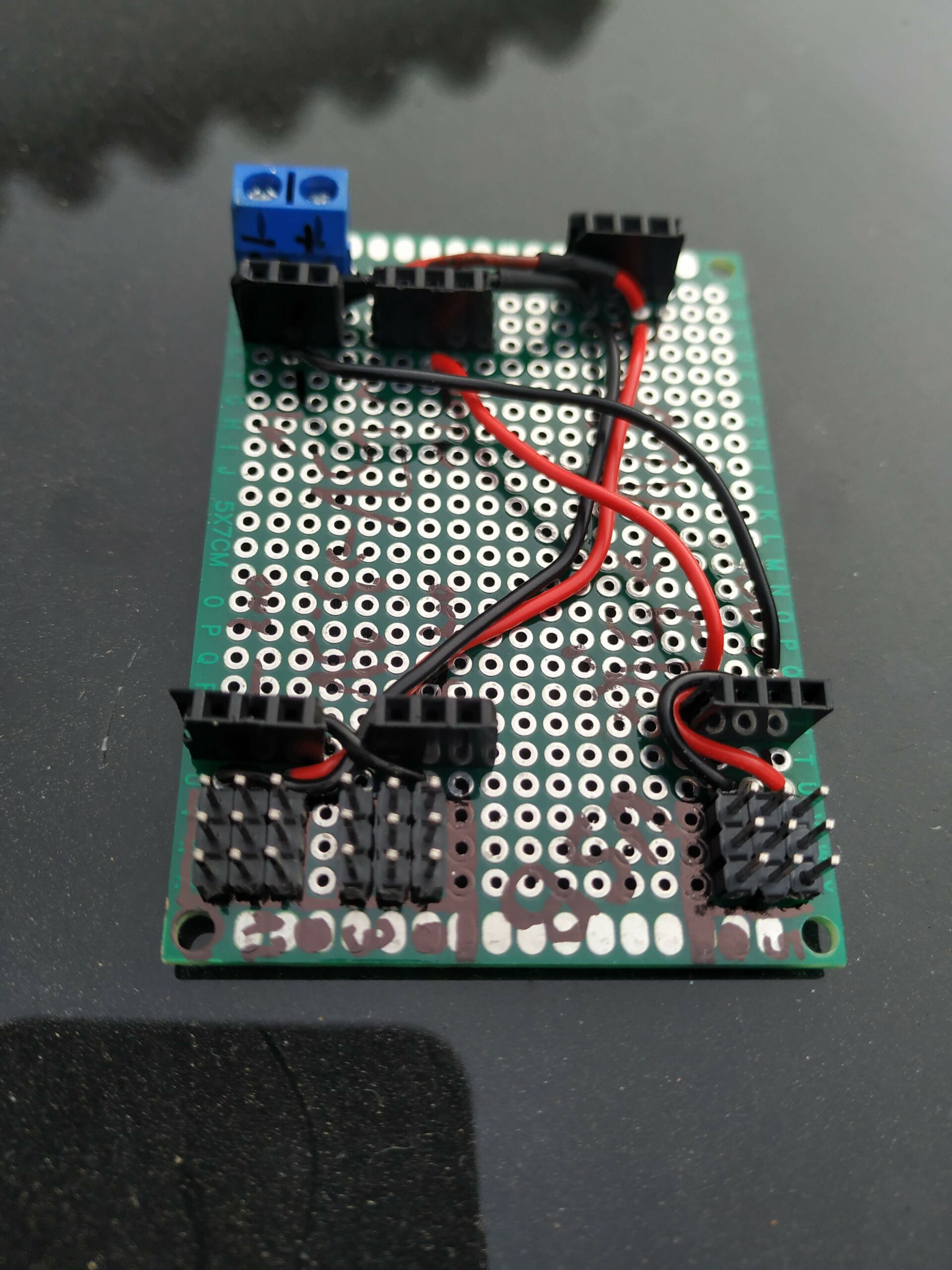
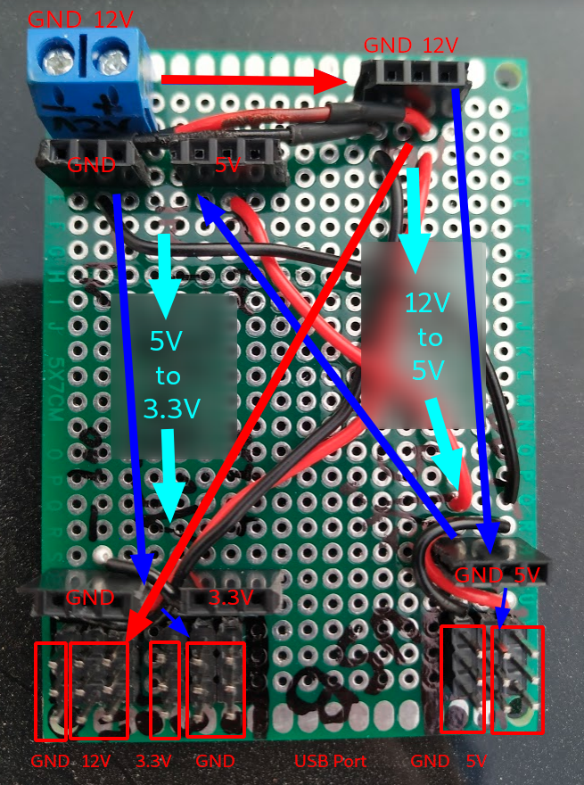
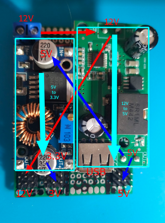
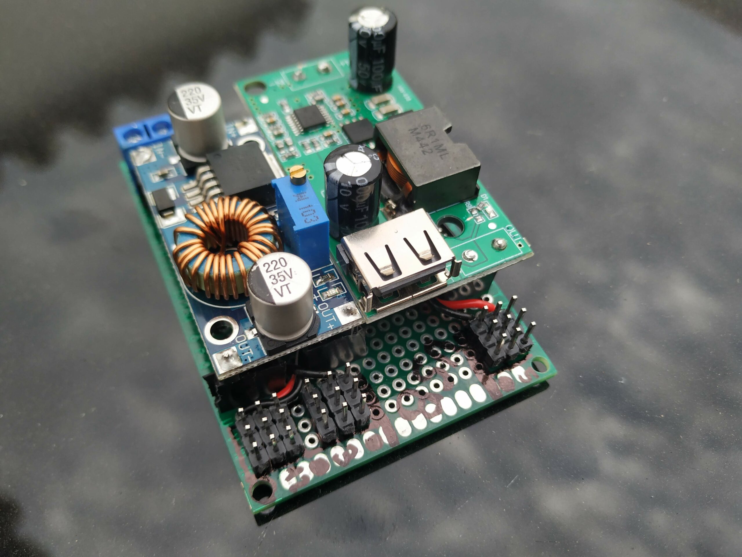
Many of my modules work with I2C, and because of that, I decided to make a board just for all of those. In addition, I thought it was a good idea to attach the RS485 communication board to compacter the final result. To build this board, I used wires (30AWG 0.05mm²) with a silicone cover, making it easier to sell and manage. Some of the sensors work at 3.3V, so I have used a level converter to communicate 3.3V sensors with the rest of the bus at 5.5V (you can learn more about level shifter here “How a Bidirectional Logic Level Converter works? Logic Level Shifter“). WARNING: watch out, SDA & SCL are in different colours to show different bus voltages:
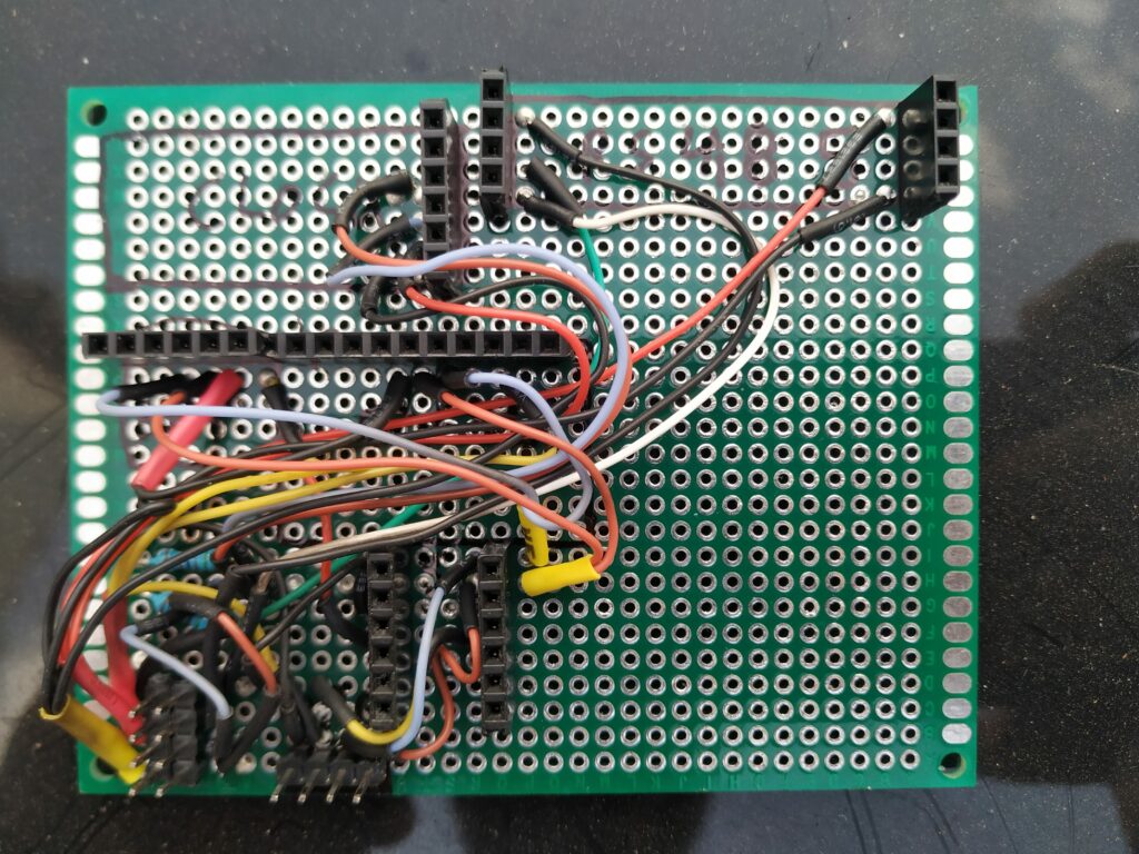
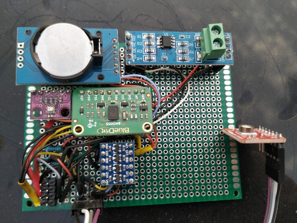
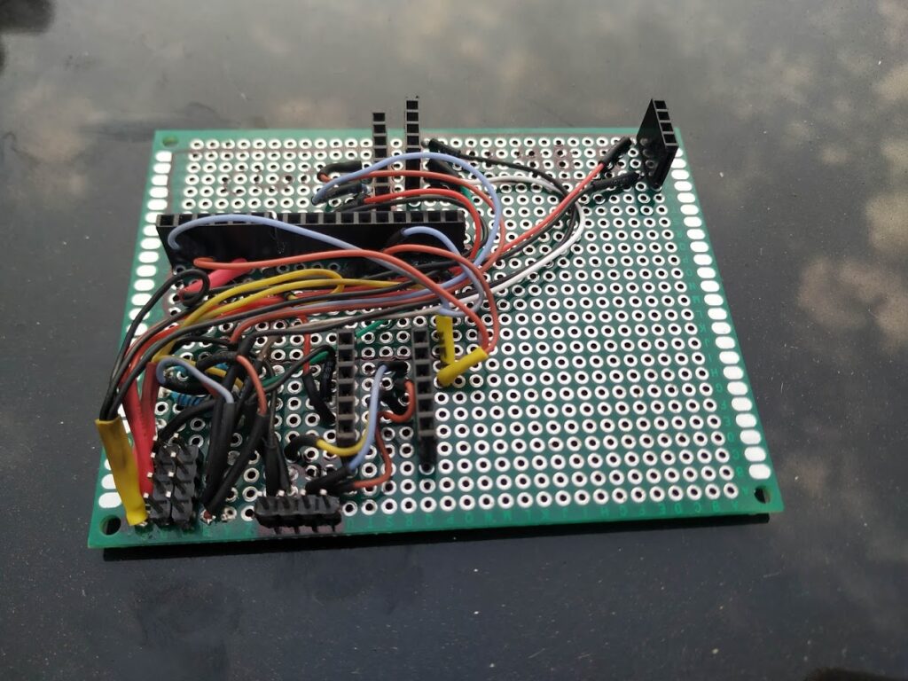
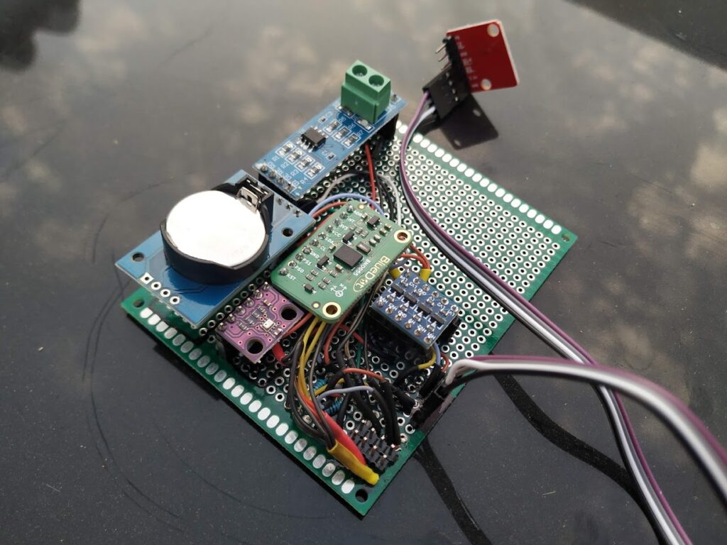
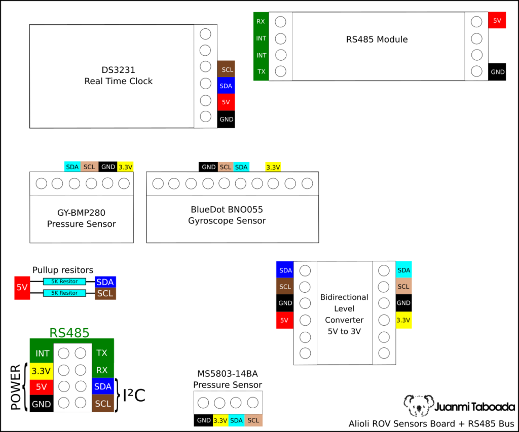
During these days, I will get Prototype Boards for Arduino Mega 2560 R3 to prepare buses and test everything with the existing software. In the next post, I will publish the rest of the hardware I have been working on, and I will interconnect everything, the “Learn how to Build an Engine Controller for your Alioli Submarine UAV Drone“.
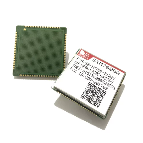
Here is how to make a SIMCOM 7600 module work on an Arduino board (Uno, Mega 2560, Leonardo, Due, Micro, Zero, Nano, Pico), ESP8266, ESP32, Raspberry Pi Pico, MicroPython, or any...
Conectar un motor paso a paso (Stepper) a un microcontrolador usando MicroPython abre la puerta a infinidad de proyectos de robótica, CNC, impresoras 3D o automatización. En este...